Electrical 3 min read
Sizing 12V Breakers on a Sailboat: Osculati or E-T-A
Choosing and sizing 12V breakers on a J/92s: separate breaker + rocker architecture, Osculati vs E-T-A, and channel-by-channel amperage logic.
Read next
Rebuilding the 12V system on a J/92s to cut fire and failure risk: star topology, dedicated feeds, layered protection and clear labelling.
A well-designed 12V system is measured by one thing: how much it cuts the risk of failure and fire. On Jamais, a 2008 J/92s at La Pichette on Lake Geneva, the 2026 refit began with one dead symptom — an autopilot that would no longer power up — and opened a Pandora’s box: the wiring behind the panel was a genuine fire hazard. This post documents each decision and why it was made.
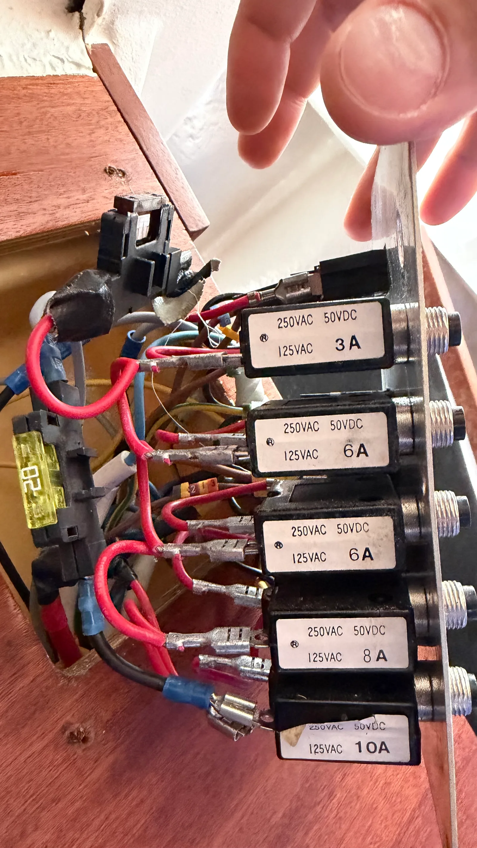
The original wiring was a stack of patches. A heavy cable left the battery switch and was reduced to 1.5 mm² at the very first fuse — an unprotected transition that could overheat before anything tripped. Positives were bridged fuse-to-fuse in progressive undersizing. Negatives were bridged across the switch terminals, with no real ground bus. Flying blade fuses had been added over the years, and the autopilot stayed live with every breaker off, through a hidden, intermittent fuse. Fixing any one of these locally would have left the rest — so the answer was architectural.
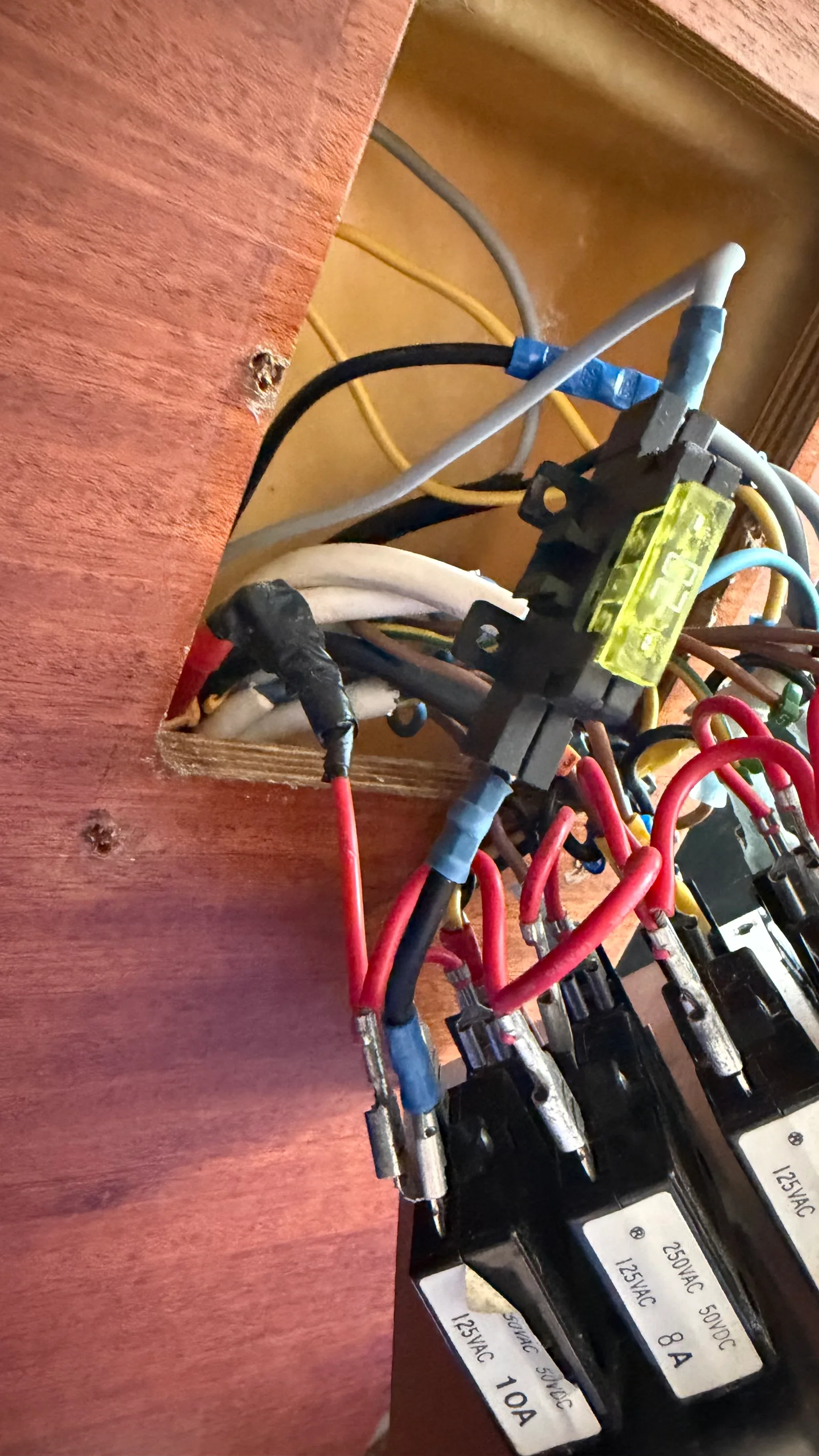
The guiding principle is star topology: every circuit leaves from and returns to a single distribution point, instead of daisy-chaining loads. Two Osculati bus bars (identical for + and −) are those points. The positive bus lives in the existing fibreglass box behind the panel; the negative bus sits in an IP66 box in the starboard aft locker, where the boat’s wiring naturally converges.
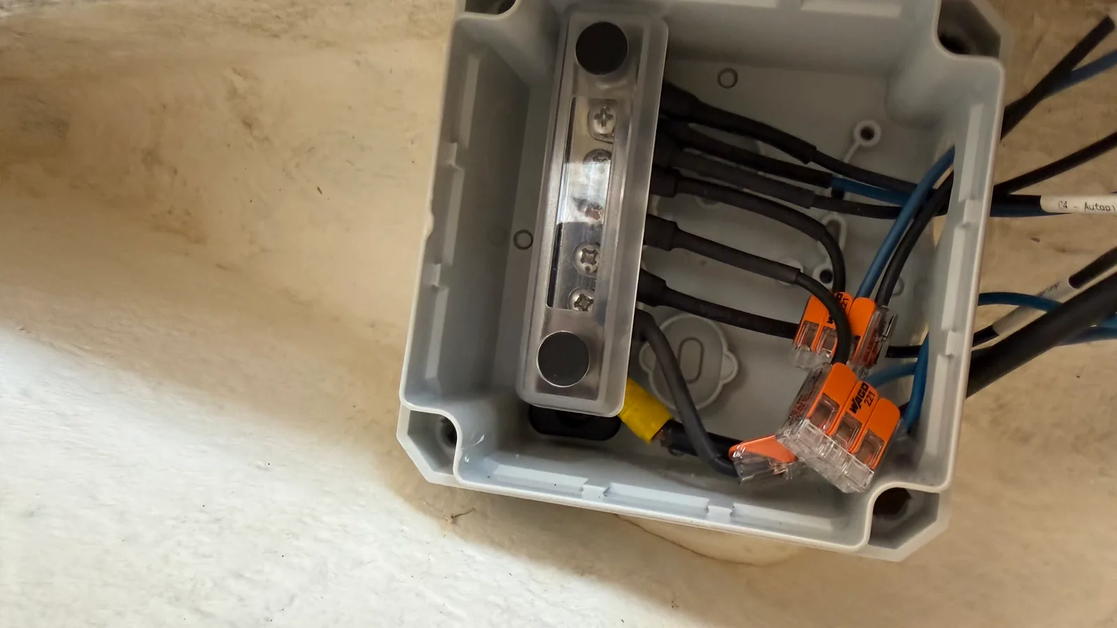
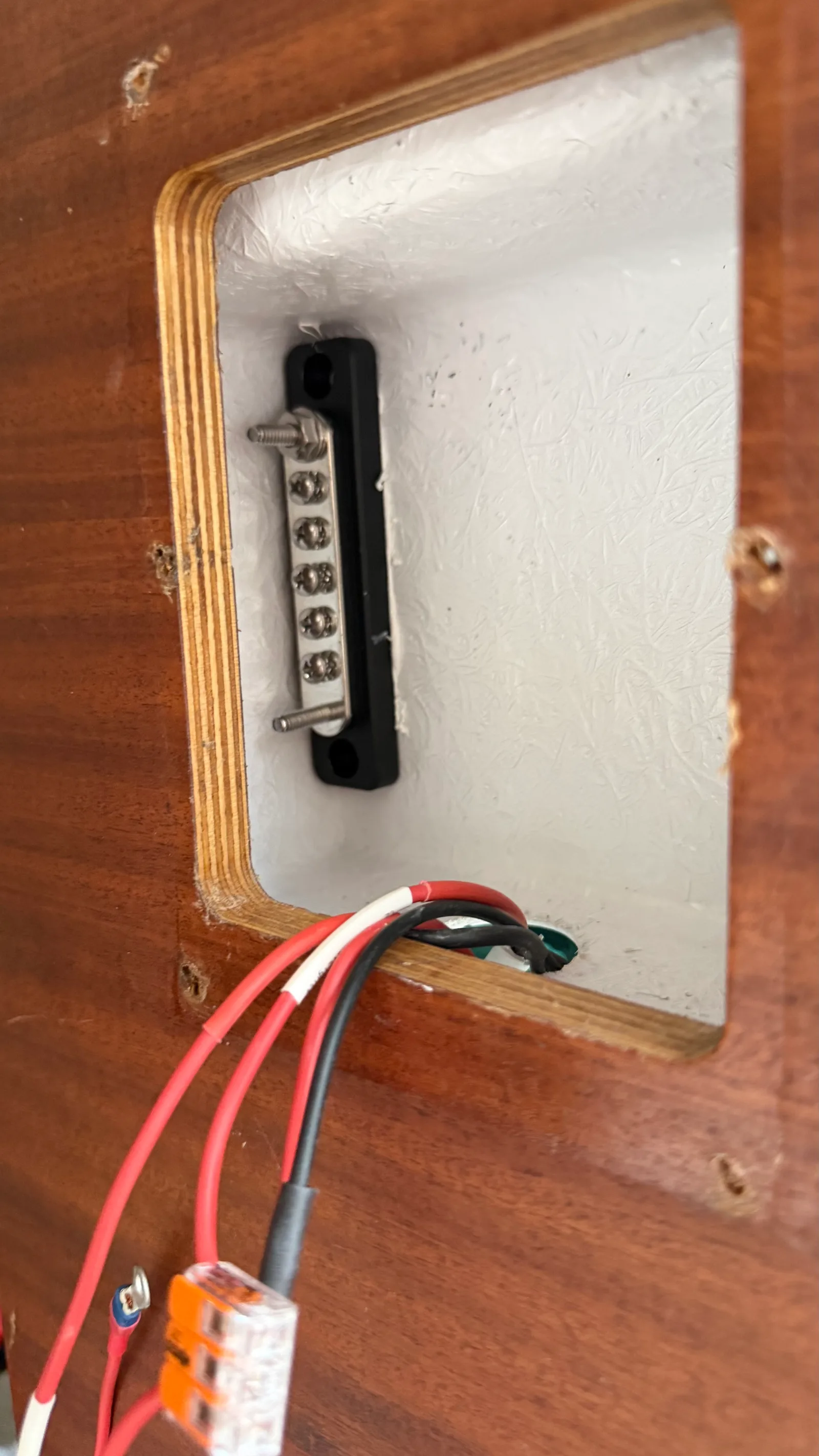
The battery feed is 6 mm² tinned marine, through the dual-pole battery switch to the positive bus. From there, distribution is in 1.5 mm² — sized for the real current, length and type of each branch, not to a habit.
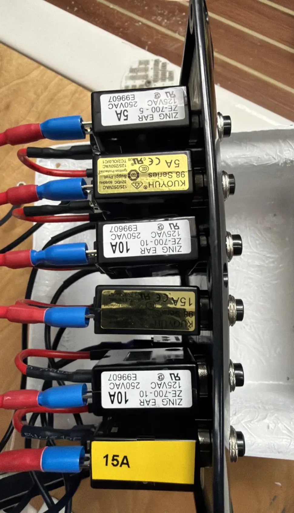
The new panel arrived wired the way most are: the positive feed lands in the centre, on breakers 3 and 4, then jumps outward to breakers 1–2 and 5–6. That means breakers 3 and 4 don’t just carry their own load — they carry the cumulative current of the neighbouring channels. It is the same chain-and-undersize logic we had just torn out of the old boat.
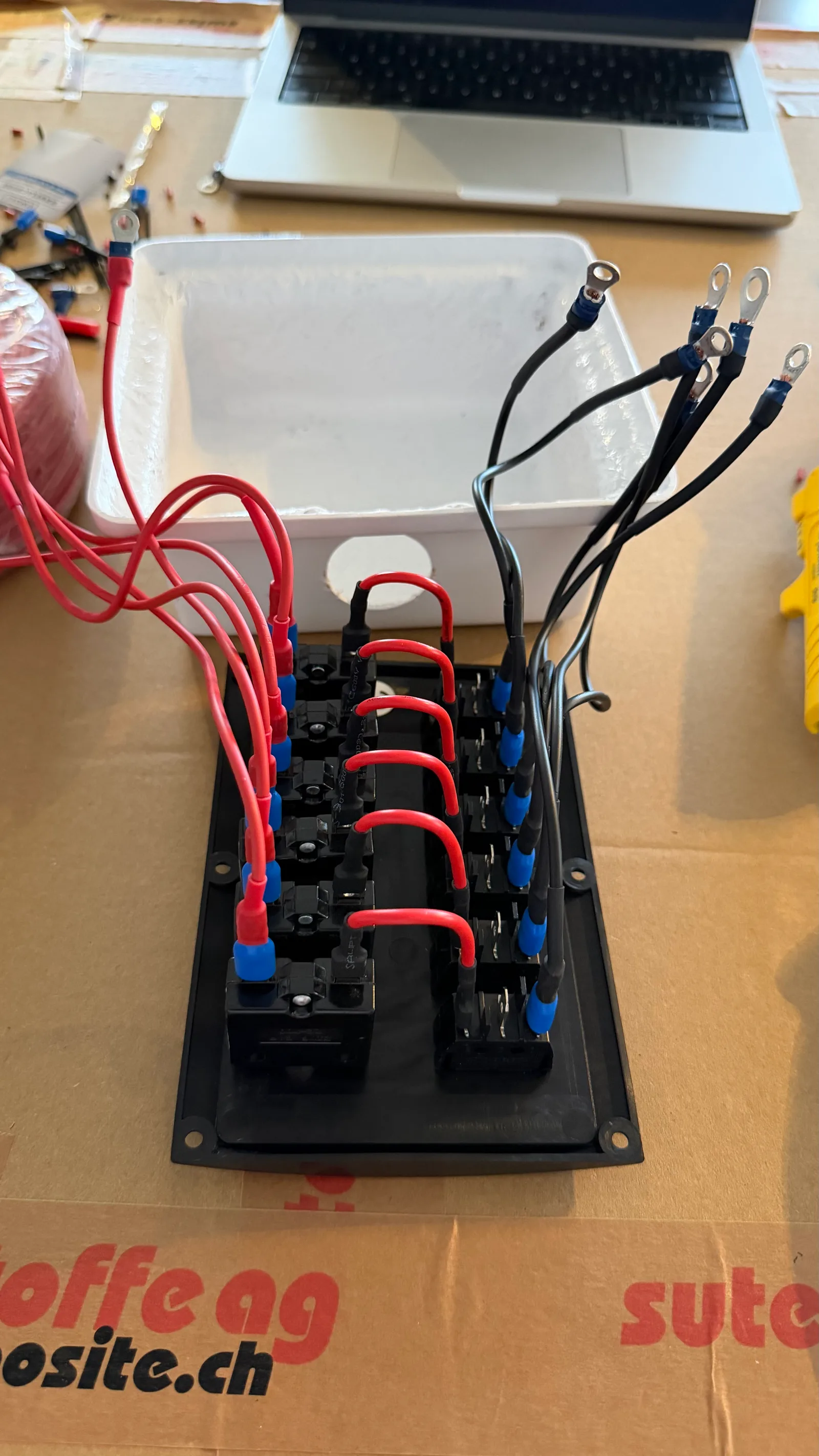
So the panel was modified: a dedicated 1.5 mm² feed runs from the positive bus to each breaker. No channel carries another channel’s current. Yes, it means taking tools to a panel fresh out of the box — but that is precisely the point of a rebuild done properly.
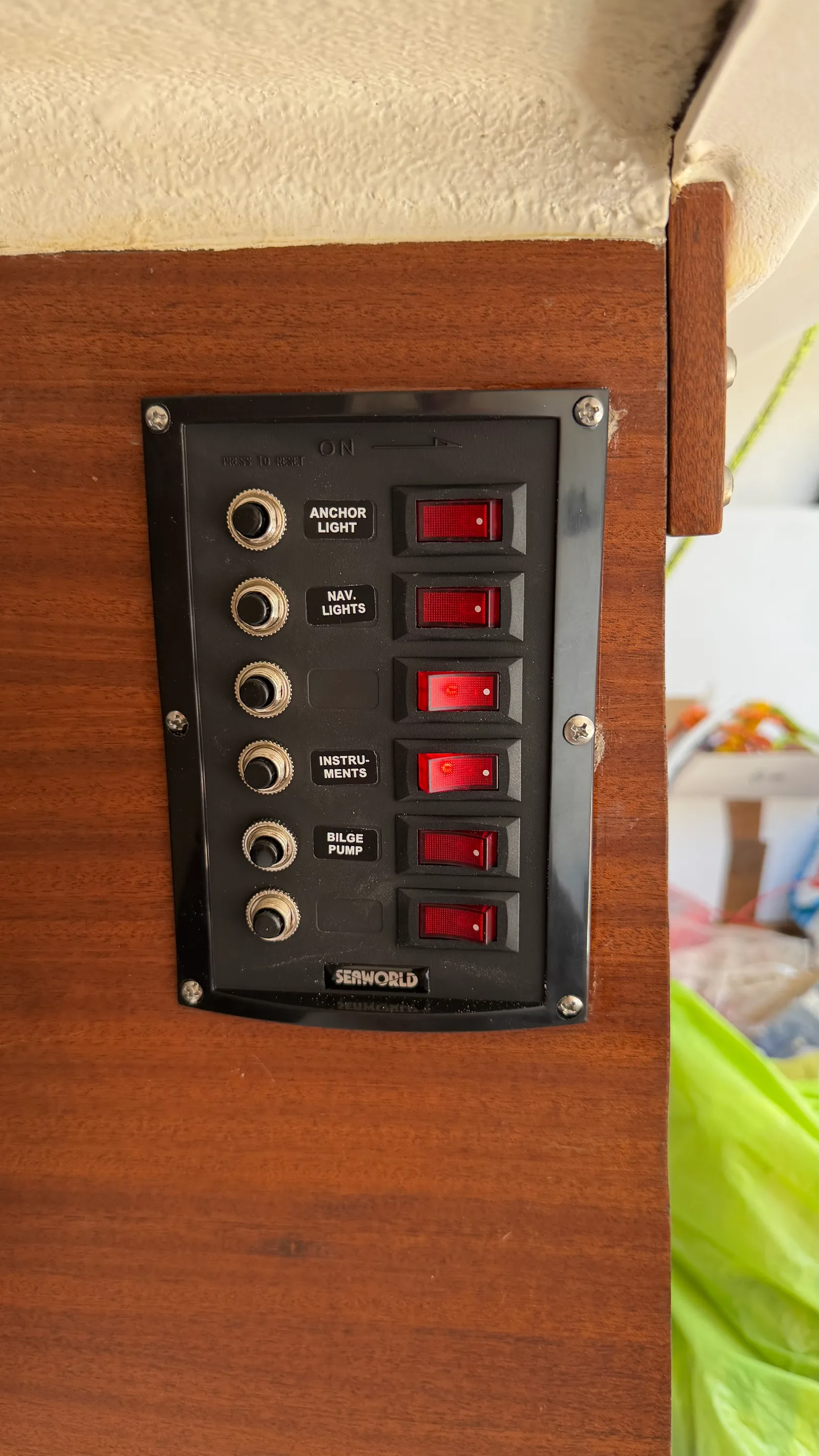
The existing 6-position panel was reused, keeping the architecture that separates breaker from rocker switch. The path is feed → breaker → rocker → load; some loads split downstream through a WAGO 221 (Ch3 aggregates the cabin loop, the reading light and the USB socket).
With a dedicated negative bus in place, the panel’s own chain of negative jumpers across the rockers was kept — but only to feed the rocker indicator LEDs, a few milliamps. It is not a ground bus. The real load negatives run to the negative bus individually, or grouped per channel through a WAGO. Keeping the little LED-return chain avoids a nest of extra wire behind the panel, while the actual return current goes where it belongs.
The Rule 800 Auto has three wires. Its AUTO positive runs straight from the bus, on its own 7.5 A fuse in an waterproof holder, so the pump works on its float switch even with the panel off. Its MANUAL positive comes from Ch5, as an override. One accepted lake compromise: auto mode still depends on the battery switch being ON — which the 2027 lithium distributor will remove.
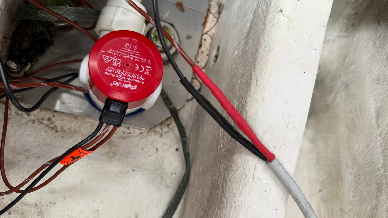
Bad architecture wasn’t the only problem: much of the old wiring simply ran where cable should never run. Several old two-core (bipolar) cables were replaced along their full length — not because the wire had failed, but because their routes had. The stern nav-light and autopilot cables passed through the engine bay’s heat, oil and diesel; the aft-berth reading-light cable ran between the engine and the sail drive, glued down its whole length in Sikaflex. Each was re-run on a clean, high route instead.
The protection is then calibrated to each run, not applied by rote. The cables crossing the engine bay get the full silicone-sleeve treatment (below); but a low-current, dry branch like the aft-berth light — around half an amp, now routed high along the engine-bay ceiling — is served by a fire-retardant cable and an added flame-retardant sleeve. Enough for the risk, without over-building a circuit that doesn’t need it.
The refit’s thermal logic runs through the whole system, not just the engine bay:
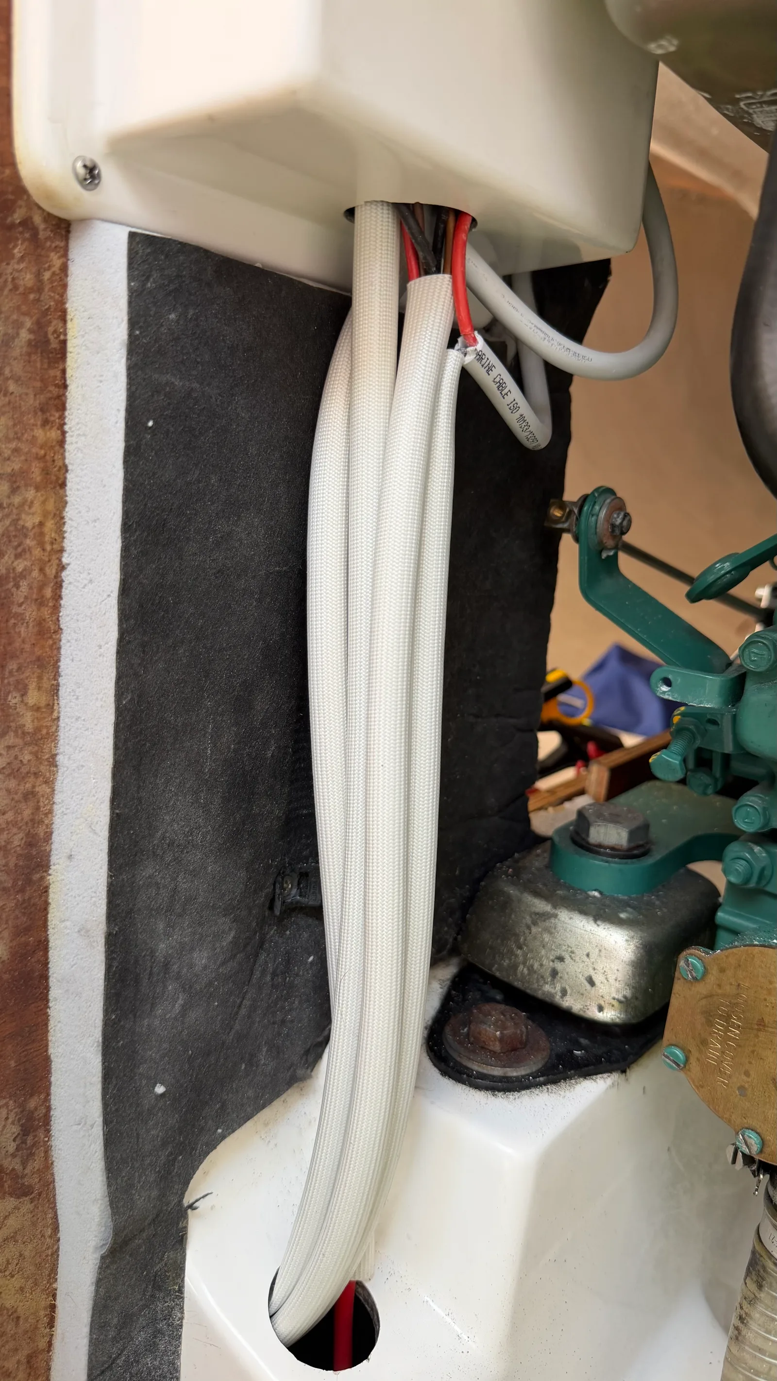
A system you cannot read is a system you cannot fix. Every cable is labelled with a coherent per-channel naming convention — [PREFIX]-[LOAD].[SUB]±, with C1–C6 for the panel channels, AUX for direct-from-bus branches, polarity always the last character — printed on a Brother PT-E310BTVP in heat-shrink cassette. Years from now, any wire traces without reverse-engineering the boat.
All downstream wiring — the C1–C6 labels, both bus bars — stays identical through the 2027 lithium conversion (Victron LiFePO4, Class T fuse, Lynx BMS). Only the upstream distribution changes. That constraint was set from the start.
What cable size for a 12V circuit? There is no single “correct” section: it depends on the load’s current, the cable’s length and the type of load. Each branch here was sized with a wire-size calculator, not to a rule of thumb.
Why separate positive and negative bus bars? Two distinct bars make the star topology physical and give a clean disconnection point for each polarity.
Why bother modifying a brand-new panel? Because its factory central feed makes breakers 3 and 4 carry the neighbouring channels’ current. A dedicated feed per breaker removes that, so no channel is undersized by another’s load.
This refit is part of Jamais’s logbook. See also the companion article on choosing and sizing 12V breakers.
Choosing and sizing 12V breakers on a J/92s: separate breaker + rocker architecture, Osculati vs E-T-A, and channel-by-channel amperage logic.
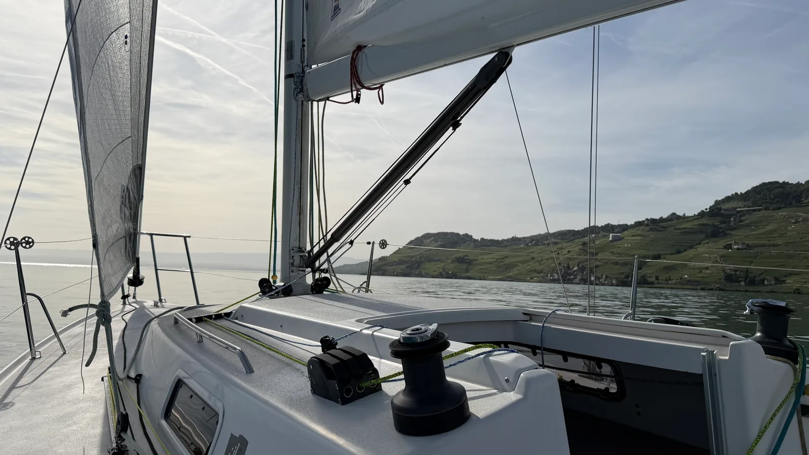
Rebuilding a J/92s cockpit: Spinlock XTS clutches and a Dyneema cascade vang for more power and a cleaner, more ergonomic deck layout.
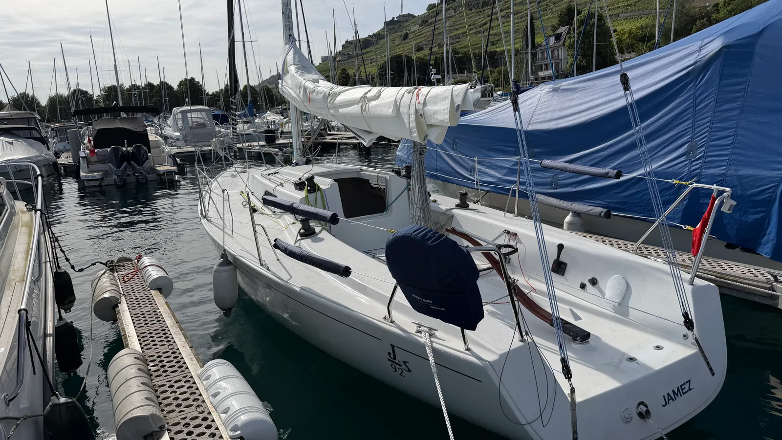
Restoring a J/92s stern safety station: an Osculati horseshoe buoy kit, a straightened stanchion, and a re-welded stern-light plate.
Order your parts, or let’s talk through your programme first.